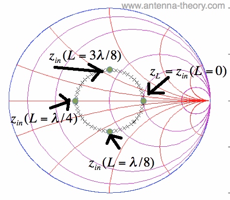
The Input Impedance plot is looking at the impedance looking into port 1 of the schematic. The Normalized graph is showing the s-parameters of the line on a smith chart. In the project, please see the graphs Normalized and Input Impedance. Techniques 2 and 3 are discussed in more detail below. Set the port impedances on either side of the line to be a variable and tune or optimize the impedance until the line is perfectly matched, the value of the port impedances is the characteristic impedance of your line. Then using the quarter wavelength transformer equation, calculate the characteristic impedance of the line.ģ. Determine the impedance looking into one side of the line at the frequency where the line is quarter wavelength long. This approach will not work if you are only given s-parameters and have to determine the impedance only from the frequency response of the line.Ģ. Please select Tools > TXLine to access this software.
#Smith chart transmission line software#
TXLINE is a free addition to AWR software that allows the user to enter geometry and calculate impedance or vice-versa. The AWR design environment has several ways you can calculate a line's characteristic impedance.ġ.

This example will demonstrate with a CPW line, but the approach is general and can be applied to any transmission line structure, such as microstrip, stripline, coax, etc. This example will show users several ways of determining the characteristic impedance of a transmission line. Transmission Line Characteristic Impedance

Where To Find This Example Download Project


 0 kommentar(er)
